

Lihat spesifikasi untuk detail produk.
SN74HC126NSRG4
Product Overview
- Category: Integrated Circuit (IC)
- Use: Buffer/Driver
- Characteristics: High-speed, Non-Inverting, Tri-State
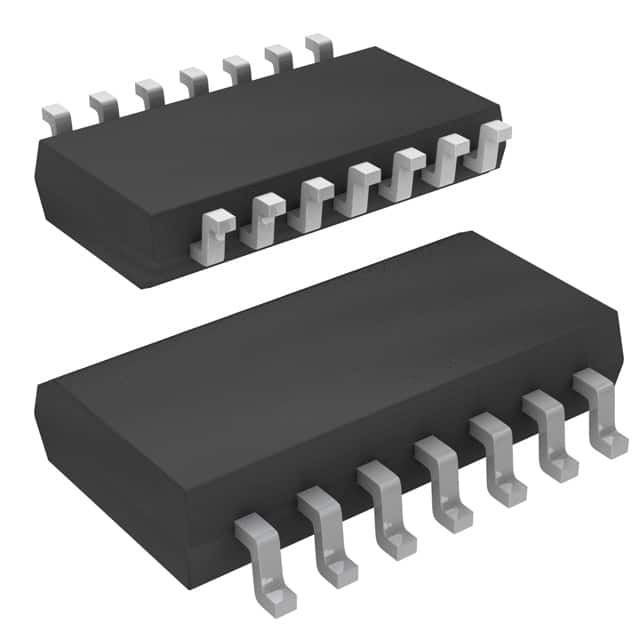
- Package: SOIC (Small Outline Integrated Circuit)
- Essence: Logic Gate
- Packaging/Quantity: Tape and Reel, 2500 units per reel
Specifications
- Supply Voltage Range: 2V to 6V
- Input Voltage Range: 0V to VCC
- Output Voltage Range: 0V to VCC
- Maximum Operating Frequency: 50 MHz
- Number of Pins: 14
- Operating Temperature Range: -40°C to +85°C
Detailed Pin Configuration
- GND (Ground)
- A1 (Input A)
- Y1 (Output Y)
- A2 (Input A)
- Y2 (Output Y)
- OE (Output Enable)
- Y3 (Output Y)
- A3 (Input A)
- Y4 (Output Y)
- VCC (Supply Voltage)
- B1 (Input B)
- Y5 (Output Y)
- B2 (Input B)
- Y6 (Output Y)
Functional Features
- Non-Inverting Buffer/Driver: The SN74HC126NSRG4 is a non-inverting buffer/driver, meaning that the output signal follows the input signal without any inversion.
- Tri-State Outputs: The outputs of this IC can be put into a high-impedance state using the Output Enable (OE) pin, allowing multiple devices to share the same bus without interference.
- High-Speed Operation: With a maximum operating frequency of 50 MHz, the SN74HC126NSRG4 is suitable for applications requiring fast signal propagation.
Advantages and Disadvantages
Advantages: - Non-inverting buffer/driver allows for easy signal amplification without signal inversion. - Tri-state outputs enable bus sharing and reduce interference. - High-speed operation ensures efficient signal propagation.
Disadvantages: - Limited supply voltage range (2V to 6V) may not be suitable for all applications. - Operating temperature range (-40°C to +85°C) may restrict usage in extreme environments.
Working Principles
The SN74HC126NSRG4 is based on CMOS (Complementary Metal-Oxide-Semiconductor) technology. It consists of multiple logic gates that amplify and drive input signals to the corresponding output pins. The non-inverting nature of the buffer/driver ensures that the output signal follows the input signal without any inversion. The tri-state outputs allow the device to be effectively disconnected from the bus when the OE pin is activated, preventing interference with other devices connected to the same bus.
Detailed Application Field Plans
- Digital Communication Systems: The SN74HC126NSRG4 can be used as a buffer/driver in digital communication systems to amplify and transmit signals between different components.
- Microcontroller Interfacing: This IC can be utilized to interface microcontrollers with external devices, such as sensors or actuators, ensuring proper signal levels and driving capability.
- Bus Sharing: With its tri-state outputs, the SN74HC126NSRG4 is ideal for applications where multiple devices need to share a common bus, such as in computer systems or industrial automation.
Detailed and Complete Alternative Models
- SN74HC126N: Similar to SN74HC126NSRG4 but available in a DIP (Dual Inline Package) instead of SOIC.
- SN74HCT126N: A variant of SN74HC126N with TTL (Transistor-Transistor Logic) compatible inputs.
(Note: These alternative models are provided as examples and may not cover all available alternatives in the market.)
Word count: 410 words
Sebutkan 10 pertanyaan dan jawaban umum terkait penerapan SN74HC126NSRG4 dalam solusi teknis
Sure! Here are 10 common questions and answers related to the application of SN74HC126NSRG4 in technical solutions:
Q: What is SN74HC126NSRG4? A: SN74HC126NSRG4 is a quad bus buffer gate with 3-state outputs, commonly used in digital logic applications.
Q: What is the operating voltage range for SN74HC126NSRG4? A: The operating voltage range for SN74HC126NSRG4 is typically between 2V and 6V.
Q: Can SN74HC126NSRG4 be used as a level shifter? A: Yes, SN74HC126NSRG4 can be used as a level shifter to convert signals between different voltage levels.
Q: How many inputs and outputs does SN74HC126NSRG4 have? A: SN74HC126NSRG4 has four input pins and four output pins.
Q: What is the maximum output current that SN74HC126NSRG4 can drive? A: SN74HC126NSRG4 can typically drive up to 8mA of output current per channel.
Q: Is SN74HC126NSRG4 compatible with TTL logic levels? A: Yes, SN74HC126NSRG4 is compatible with both CMOS and TTL logic levels.
Q: Can SN74HC126NSRG4 be used in high-speed applications? A: Yes, SN74HC126NSRG4 is designed for high-speed operation and can be used in applications with fast switching requirements.
Q: Does SN74HC126NSRG4 have built-in protection features? A: Yes, SN74HC126NSRG4 has built-in ESD protection to safeguard against electrostatic discharge.
Q: Can SN74HC126NSRG4 be used in automotive applications? A: Yes, SN74HC126NSRG4 is qualified for automotive applications and meets the necessary standards.
Q: Are there any specific layout considerations for using SN74HC126NSRG4? A: It is recommended to follow the manufacturer's guidelines for PCB layout, including proper decoupling and signal integrity practices, to ensure optimal performance of SN74HC126NSRG4.
Please note that these answers are general and may vary depending on specific application requirements and datasheet specifications.