Lihat spesifikasi untuk detail produk.

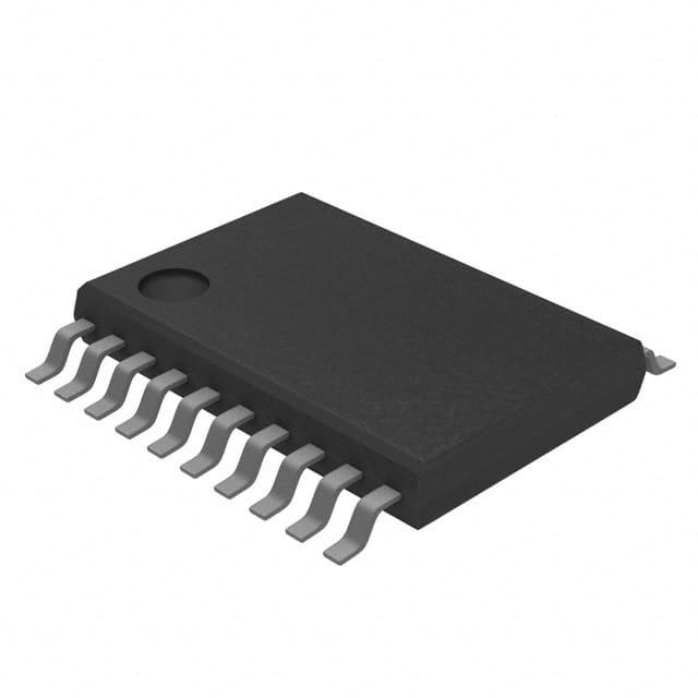
CD74HC377PWG4
Product Overview
Category
CD74HC377PWG4 belongs to the category of integrated circuits (ICs).
Use
It is commonly used in digital electronic systems for data storage and manipulation.
Characteristics
- High-speed operation
- Wide operating voltage range
- Low power consumption
- Compatibility with various logic families
- Schmitt-trigger inputs for noise immunity
Package
CD74HC377PWG4 is available in a small outline package (SOIC) with a wide body, allowing for easy handling and soldering.
Essence
The essence of CD74HC377PWG4 lies in its ability to store and manipulate data in digital systems efficiently.
Packaging/Quantity
It is typically packaged in reels or tubes, with a quantity of 2500 units per reel or 98 units per tube.
Specifications
- Supply Voltage Range: 2V to 6V
- High-Level Input Voltage: 3.15V (minimum), 5.25V (maximum)
- Low-Level Input Voltage: 0.45V (maximum), 1.35V (minimum)
- High-Level Output Voltage: 4.4V (minimum), VCC (maximum)
- Low-Level Output Voltage: 0.55V (maximum), 0V (minimum)
- Operating Temperature Range: -40°C to +85°C
Detailed Pin Configuration
CD74HC377PWG4 has a total of 20 pins, which are assigned specific functions as follows:
- CP (Clock Pulse) - Clock input for data storage and manipulation.
- D0-D7 (Data Inputs) - Inputs for storing data.
- OE (Output Enable) - Enables the output of stored data.
- Q0-Q7 (Data Outputs) - Outputs for the stored data.
- MR (Master Reset) - Resets the stored data to a predefined state.
- GND (Ground) - Reference voltage for the IC.
- VCC (Supply Voltage) - Power supply input.
Functional Features
- Data Storage: CD74HC377PWG4 can store data on its eight D-inputs and retain it until a new set of data is provided.
- Data Manipulation: It allows for various operations on the stored data, such as reading, writing, and resetting.
- Output Enable: The OE pin enables or disables the output of stored data, providing control over when the data is visible to other components.
- Schmitt-Trigger Inputs: These inputs ensure noise immunity by providing hysteresis and reducing the impact of signal fluctuations.
Advantages and Disadvantages
Advantages
- High-speed operation allows for efficient data processing.
- Wide operating voltage range provides flexibility in different electronic systems.
- Low power consumption contributes to energy efficiency.
- Compatibility with various logic families simplifies integration into existing designs.
- Schmitt-trigger inputs enhance noise immunity, ensuring reliable operation.
Disadvantages
- Limited storage capacity compared to other memory devices.
- Lack of non-volatile storage capability, requiring external means for data retention during power loss.
Working Principles
CD74HC377PWG4 operates based on the principles of digital logic circuits. The clock pulse (CP) triggers the storage of data from the D-inputs into internal flip-flops. The stored data can be manipulated through various operations, such as reading or writing, controlled by the OE pin. The master reset (MR) pin resets the stored data to a predefined state.
Detailed Application Field Plans
CD74HC377PWG4 finds applications in various digital electronic systems, including but not limited to: - Microcontrollers - Data storage devices - Communication systems - Control units - Arithmetic logic units
Detailed and Complete Alternative Models
Some alternative models to CD74HC377PWG4 that serve similar functions include: - 74HC377 - SN74HC377 - MC74HC377 - CD54HC377
These models offer comparable features and can be used as substitutes depending on specific requirements.
Word count: 550 words
Sebutkan 10 pertanyaan dan jawaban umum terkait penerapan CD74HC377PWG4 dalam solusi teknis
Sure! Here are 10 common questions and answers related to the application of CD74HC377PWG4 in technical solutions:
Q: What is CD74HC377PWG4? A: CD74HC377PWG4 is a high-speed CMOS octal D-type flip-flop with 3-state outputs, commonly used in digital logic applications.
Q: What is the operating voltage range for CD74HC377PWG4? A: The operating voltage range for CD74HC377PWG4 is typically between 2V and 6V.
Q: What is the maximum clock frequency supported by CD74HC377PWG4? A: CD74HC377PWG4 can support clock frequencies up to 74 MHz.
Q: How many flip-flops are there in CD74HC377PWG4? A: CD74HC377PWG4 consists of eight individual D-type flip-flops.
Q: What are the typical applications of CD74HC377PWG4? A: CD74HC377PWG4 is commonly used in applications such as data storage, address decoding, and general-purpose register applications.
Q: What is the output drive capability of CD74HC377PWG4? A: CD74HC377PWG4 has a typical output drive capability of ±6 mA.
Q: Does CD74HC377PWG4 have any built-in protection features? A: Yes, CD74HC377PWG4 has built-in diode protection to prevent damage from static discharge.
Q: Can CD74HC377PWG4 be cascaded to increase the number of flip-flops? A: Yes, CD74HC377PWG4 can be cascaded to increase the number of flip-flops in a system.
Q: What is the power supply current consumption of CD74HC377PWG4? A: The power supply current consumption of CD74HC377PWG4 is typically around 8 mA.
Q: Is CD74HC377PWG4 compatible with other logic families? A: Yes, CD74HC377PWG4 is compatible with other CMOS logic families and can interface with TTL inputs when appropriate level shifting is used.
Please note that these answers are general and may vary depending on specific datasheet specifications and application requirements.

