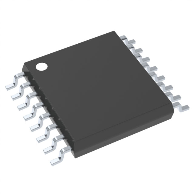
Lihat spesifikasi untuk detail produk.

CD4033BPWR
Basic Information Overview
- Category: Integrated Circuit (IC)
- Use: Decade Counter/Divider
- Characteristics: CMOS technology, low power consumption, high noise immunity
- Package: TSSOP (Thin Shrink Small Outline Package)
- Essence: A 5-stage Johnson decade counter with decoded outputs
- Packaging/Quantity: Tape and reel packaging, 2500 units per reel
Specifications
- Supply Voltage Range: 3V to 18V
- Operating Temperature Range: -55°C to +125°C
- Maximum Clock Frequency: 5MHz
- Output Current: ±6mA
- Input Capacitance: 3pF
- Propagation Delay Time: 60ns
Detailed Pin Configuration
- VDD: Positive supply voltage
- GND: Ground reference
- CLOCK: Clock input for counting
- RESET: Reset input, clears the counter to zero
- ENABLE: Enable input, controls the counting operation
- BCD Outputs (Q0-Q3): Binary-coded decimal outputs
- CARRY OUT: Carry output, indicates overflow of the counter
Functional Features
- Decodes and displays a 4-bit binary-coded decimal (BCD) value
- Counts in a decade sequence from 0 to 9
- Provides decoded outputs for each BCD digit
- Supports cascading multiple CD4033B devices for larger count ranges
- Low power consumption due to CMOS technology
- High noise immunity ensures reliable operation in noisy environments
Advantages
- Compact and space-saving TSSOP package
- Wide supply voltage range allows flexibility in various applications
- Simple interface with clock, reset, and enable inputs
- Easy integration with other digital circuits
- Low power consumption extends battery life in portable devices
Disadvantages
- Limited count range from 0 to 9, not suitable for applications requiring larger counts
- Propagation delay time may affect timing-sensitive applications
- Lack of built-in display drivers, requires external driver circuitry for visual output
Working Principles
The CD4033BPWR is a synchronous decade counter/divider that operates based on the clock input. On each rising edge of the clock signal, the counter advances by one count. The reset input clears the counter to zero, and the enable input controls the counting operation.
The BCD outputs (Q0-Q3) provide the decoded representation of the current count value. These outputs can be directly connected to display drivers or other digital circuits for further processing.
The carry output indicates an overflow condition when the counter reaches its maximum count of 9. This carry output can be used to cascade multiple CD4033B devices to achieve larger count ranges.
Detailed Application Field Plans
- Digital clocks and timers: The CD4033BPWR can be used to drive the display of hours, minutes, and seconds in digital clocks and timers.
- Frequency dividers: By connecting the clock input to a higher frequency signal, the CD4033BPWR can divide the input frequency by 10, providing a lower frequency output.
- Industrial automation: The counter can be utilized in various industrial automation systems for counting and monitoring purposes.
- Sequential control systems: The CD4033BPWR can be employed in sequential control systems where a specific sequence of events needs to be executed.
Detailed and Complete Alternative Models
- CD4026B: Similar to CD4033B but with a 7-segment display decoder/driver included.
- CD4017B: Decade counter with 10 decoded outputs, suitable for more complex counting applications.
- CD4518B: Dual BCD up-counter with presettable counters, useful for applications requiring preset count values.
(Note: The above alternative models are just a few examples; there are several other alternatives available in the market.)
This entry provides an overview of CD4033BPWR, a decade counter/divider IC. It includes basic information, specifications, pin configuration, functional features, advantages and disadvantages, working principles, application field plans, and alternative models.
Sebutkan 10 pertanyaan dan jawaban umum terkait penerapan CD4033BPWR dalam solusi teknis
Sure! Here are 10 common questions and answers related to the application of CD4033BPWR:
Q: What is CD4033BPWR? A: CD4033BPWR is a CMOS decade counter/divider integrated circuit (IC) commonly used in digital electronics applications.
Q: What is the maximum supply voltage for CD4033BPWR? A: The maximum supply voltage for CD4033BPWR is typically 18V.
Q: How many outputs does CD4033BPWR have? A: CD4033BPWR has 7 decoded outputs, representing the decimal values from 0 to 9.
Q: Can CD4033BPWR be used as a frequency divider? A: Yes, CD4033BPWR can be used as a frequency divider by connecting the input clock signal to the CLK pin.
Q: What is the maximum clock frequency for CD4033BPWR? A: The maximum clock frequency for CD4033BPWR is typically around 5 MHz.
Q: How can I reset the counter in CD4033BPWR? A: The counter in CD4033BPWR can be reset by connecting the RESET pin to a logic low (GND).
Q: Can CD4033BPWR drive LEDs directly? A: No, CD4033BPWR cannot drive LEDs directly. It requires current-limiting resistors or additional driver circuits to drive LEDs.
Q: What is the purpose of the carry-out pin in CD4033BPWR? A: The carry-out pin (PIN 12) in CD4033BPWR is used to cascade multiple CD4033BPWR ICs together for counting beyond 9.
Q: Can CD4033BPWR be used in battery-powered applications? A: Yes, CD4033BPWR can be used in battery-powered applications as it operates at low power and has a wide supply voltage range.
Q: What are some common applications of CD4033BPWR? A: CD4033BPWR is commonly used in applications such as digital clocks, frequency dividers, scoreboards, and counter circuits.
Please note that the answers provided here are general and may vary depending on specific datasheet specifications and application requirements.

