

Lihat spesifikasi untuk detail produk.
Encyclopedia Entry: 74F657SPC
Product Overview
Category
The 74F657SPC belongs to the category of integrated circuits (ICs) and specifically falls under the family of digital logic multiplexers/demultiplexers.
Use
This product is primarily used in digital electronic systems for data routing and selection purposes. It enables the transmission of multiple data inputs through a single output line, or vice versa.
Characteristics
- The 74F657SPC is a high-speed, quad 2-input multiplexer/demultiplexer.
- It operates on a wide voltage range, typically between 4.5V and 5.5V.
- This IC is designed to provide low power consumption and high noise immunity.
- It offers fast switching speeds and reliable performance.
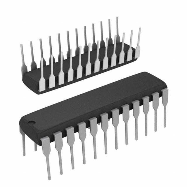
Package and Quantity
The 74F657SPC is available in a standard 16-pin small outline package (SOIC). Each package contains one unit of the IC.
Specifications
- Supply Voltage Range: 4.5V to 5.5V
- Input Voltage Range: 0V to Vcc
- Output Voltage Range: 0V to Vcc
- Operating Temperature Range: -40°C to +85°C
- Propagation Delay Time: 6 ns (max)
- Input Capacitance: 3 pF (typ)
- Output Capacitance: 8 pF (typ)
Pin Configuration
The 74F657SPC has a total of 16 pins, each serving a specific function. The pin configuration is as follows:
┌───┬───┐
 1 │1Y │GND│
 2 │2Y │A  │
 3 │3Y │B  │
 4 │4Y │C  │
 5 │G1 │D  │
 6 │G2 │E  │
 7 │G3 │F  │
 8 │G4 │Vcc│
   └───┴───┘
Functional Features
- The 74F657SPC can function as a multiplexer or demultiplexer, depending on the control inputs.
- It offers four independent data input lines (A, B, C, D) and two select lines (E, F) to control the data routing.
- The G1, G2, G3, and G4 pins are used for enabling/disabling the outputs.
- This IC provides a single output line (Y) for transmitting the selected data.
Advantages and Disadvantages
Advantages: - High-speed operation allows for efficient data transmission. - Wide voltage range compatibility enhances versatility in various electronic systems. - Low power consumption contributes to energy efficiency. - Reliable performance ensures accurate data routing.
Disadvantages: - Limited number of input/output lines may restrict complex data routing requirements. - Propagation delay time may affect real-time applications with strict timing constraints.
Working Principles
The 74F657SPC operates based on the principles of digital logic. When used as a multiplexer, the select lines (E, F) determine which data input is transmitted through the output line (Y). Conversely, when used as a demultiplexer, the select lines control which output line receives the input data. The enable pins (G1-G4) enable or disable the output lines accordingly.
Application Field Plans
The 74F657SPC finds application in various digital systems, including but not limited to: - Data communication networks - Microprocessor-based systems - Industrial automation - Instrumentation and measurement equipment - Consumer electronics
Alternative Models
For similar functionality, the following alternative models can be considered: - 74HC157: Quad 2-input multiplexer/demultiplexer - CD4051B: Single 8-channel analog multiplexer/demultiplexer - SN74LS151: 8-line to 1-line data selector/multiplexer
These alternatives offer comparable features and can be suitable replacements depending on specific system requirements.
In conclusion, the 74F657SPC is a versatile integrated circuit used for data routing and selection in digital electronic systems. Its high-speed operation, wide voltage range compatibility, and low power consumption make it an advantageous choice for various applications. However, its limited input/output lines and propagation delay time should be considered when selecting this IC for specific projects.
Sebutkan 10 pertanyaan dan jawaban umum terkait penerapan 74F657SPC dalam solusi teknis
Sure! Here are 10 common questions and answers related to the application of 74F657SPC in technical solutions:
Q: What is the 74F657SPC? A: The 74F657SPC is a quad 2-input multiplexer with 3-state outputs, commonly used in digital logic circuits.
Q: What is the purpose of a multiplexer? A: A multiplexer is used to select one of several input signals and route it to a single output line based on control inputs.
Q: How many inputs does the 74F657SPC have? A: The 74F657SPC has four data inputs (A0, A1, A2, A3) and two select inputs (S0, S1).
Q: How many output lines does the 74F657SPC have? A: The 74F657SPC has one 3-state output line (Y) for each data input.
Q: What are the control inputs used for? A: The select inputs (S0, S1) are used to determine which data input is routed to the output line.
Q: What is the purpose of the 3-state outputs? A: The 3-state outputs allow the output line to be disconnected from the circuit, effectively putting it in a high-impedance state.
Q: What is the maximum operating frequency of the 74F657SPC? A: The maximum operating frequency of the 74F657SPC is typically specified by the manufacturer and can vary.
Q: Can the 74F657SPC be cascaded to increase the number of inputs? A: Yes, multiple 74F657SPC chips can be cascaded together to increase the number of inputs and select lines.
Q: What is the power supply voltage range for the 74F657SPC? A: The power supply voltage range for the 74F657SPC is typically specified by the manufacturer and can vary.
Q: Are there any specific considerations for interfacing the 74F657SPC with other logic devices? A: Yes, it is important to ensure that the input and output voltage levels of the 74F657SPC are compatible with the other logic devices in the circuit.
Please note that the answers provided here are general and may vary depending on the specific datasheet and manufacturer's specifications for the 74F657SPC.